If a Yamaha R1 or R6 lower fairing starts smelling hot, showing a dull patch or changing shape after an exhaust change, replacing the panel first solves the wrong problem. The new part will face the same heat source unless the exhaust route, mounting position and heat barrier are checked as one system.
This is a diagnostic workflow, not a universal temperature or clearance specification. R1 and R6 generations use different bodywork and exhaust layouts, and aftermarket systems change those relationships again. Follow the motorcycle and exhaust manufacturers' instructions. If the pipe or panel cannot be positioned safely, consult a qualified technician before riding.
Separate four different problems
Riders often call every mark “melting,” but the evidence may point to different causes.
- Direct contact: the panel or heat barrier touches the pipe. Look for a concentrated polished, melted or abraded point.
- Radiant heat: a hot component sits close to a broad panel area without touching. Discoloration or softening may spread over a wider zone.
- Hot gas exposure: an exhaust leak or outlet path directs heat toward the bodywork. Soot can be an important clue.
- Mechanical rubbing: vibration moves the panel against a bracket, pipe or missing spacer. The mark may look like heat damage until the surface is inspected closely.
Do not diagnose by color alone. Photograph the outside and inside of the panel, the complete pipe route, the brackets and the corresponding point on the motorcycle.
Record the installation before moving anything
Work only on a cold motorcycle in a ventilated area. Support it securely and remove the key. Photograph the lower cowl installed from both sides and from underneath. Add a ruler or other scale near suspicious gaps without allowing it to touch a hot component.
Record:
- motorcycle model, year and market;
- exhaust brand and exact system or link-pipe part number;
- whether headers, catalyst, link pipe, silencer or mounting bracket changed;
- which fairing kit or original panel is installed;
- heat-barrier material already present;
- when the symptom appeared and under what riding conditions;
- any recent bracket, oil-service or bodywork work.
This record helps distinguish an installation change from a panel defect. It also prevents the original evidence from disappearing when the cowl is removed.
Remove the belly pan carefully
Support the panel as the last fasteners come out. Do not flex a warm panel; let the motorcycle cool fully. Label fasteners by location because a wrong shoulder length or missing collar can pull the lower cowl toward the exhaust.
Inspect the inner face under bright light. Mark each observation on a simple sketch:
- shiny or compressed contact point;
- browned adhesive or lifting foil edge;
- soot trail;
- softened or rippled plastic;
- cracked paint near a stressed mounting hole;
- rubbed bracket or missing spacer;
- heat barrier that stops before the actual hot zone.
The pattern matters more than a dramatic description. A single sharp point suggests a different correction from a large evenly heated area.
Check the exhaust as an assembly
An exhaust system can rotate slightly at a slip joint while still appearing installed. A silencer bracket fitted under tension can pull the link pipe toward the fairing. Headers may sit differently if joints were tightened before the complete system was aligned.
Compare the installed system with its instructions. Check that every supplied spacer, spring, clamp and bracket is present and oriented correctly. Look for witness marks where two parts have moved. Do not loosen or realign a system while hot, and do not improvise bends or washers without understanding the mounting design.
If an exhaust leak is suspected, stop and have it corrected. Hot gas and carbon monoxide are safety concerns, not cosmetic problems.
Measure clearance as a route, not one number
There is no responsible universal air-gap number for every R1, R6, exhaust and fairing combination. Instead, map the narrowest points along the pipe's route.
Use the cold, fully supported motorcycle. Check the area around joints, bends, collector or catalyst region where applicable, link pipe and mounting bracket. Consider how the engine and exhaust move relative to the bodywork when hot and under vibration.
Record the location of each narrow point. Compare left and right panel support, missing collars and bracket alignment. If the exhaust maker specifies clearances or shield placement, those instructions take priority.
| Evidence | Likely direction | What to verify next |
|---|---|---|
| Sharp inner-panel contact mark | Direct touch or movement | Pipe alignment, panel spacer, bracket and fastener location |
| Broad dull or discolored zone | Radiant heat | Heat-barrier coverage and component proximity |
| Soot line | Possible leak or gas path | Exhaust joints and professional leak inspection |
| Rub mark at mounting edge | Mechanical preload | Grommet, collar, bracket and installation sequence |
| Barrier lifting at edge | Adhesion or placement issue | Surface preparation and material instructions |
Select heat protection by verified purpose
Reflective foil, composite barrier mats and ceramic exhaust treatments serve different roles. A thin decorative foil is not automatically equivalent to a rated thermal barrier.

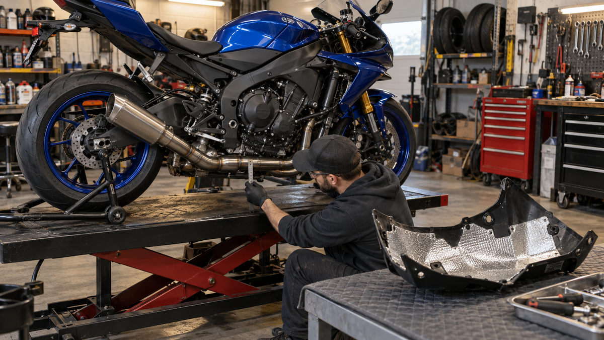
*AI-assisted editorial illustration of heat-barrier planning. It shows the workflow concept and is not a Yamaha-specific fitment template or product test.*
| Protection type | Typical role | Installation concern | What to confirm |
|---|---|---|---|
| Reflective foil tape | Covers shaped zones and seams | Wrinkles, lifting edges and adhesive rating | Temperature rating, substrate compatibility and overlap method |
| Composite heat-shield mat | Adds a thicker barrier over a defined zone | Bulk near fasteners and tight gaps | Material rating, attachment method and required clearance |
| Exhaust coating or wrap | Changes heat behavior at the exhaust component | May affect warranty, inspection and moisture management | Exhaust maker's approval and installer instructions |
Choose products with documented specifications. Do not place an adhesive material on paint or plastic unless its instructions permit that substrate and temperature range.
Prepare the inner panel without damaging it
If a new barrier is appropriate, follow the barrier maker's preparation instructions. In general, the inner surface needs to be clean, dry and free of loose adhesive. Test any cleaner in an inconspicuous area and keep aggressive solvents away from finished paint.
Make a paper template before cutting expensive material. Keep mounting holes, locating tabs, drainage paths and panel edges functional. Round sharp corners where the product instructions allow; corners are common lift points. Apply the material without trapping large air pockets, and use the specified pressure and cure time.
Never use the heat shield to pull a distorted panel flat or to hide direct exhaust contact. Correct geometry first.
Reinstall with the complete lower assembly loose
Fit the belly pan and neighboring side panels loosely. Seat all tabs and rubber receivers by hand. Verify that the heat barrier has not covered a locating surface or pushed a panel outward.
Check the narrow areas again before tightening. If tightening one fastener removes clearance elsewhere, investigate the bracket, collar and panel sequence. The bolt should retain an aligned assembly, not reshape it.
Use model-specific service information for fasteners and torque. Overtightening can compress rubber mounts and move the panel closer to the pipe.
Controlled heat-cycle inspection
Only perform a heat cycle when the exhaust is secure, no leak is suspected and the work area is ventilated. Keep a fire extinguisher appropriate for the workshop available. Do not touch the exhaust or reach near moving components.
Run the motorcycle according to the relevant service and exhaust instructions. Watch from a safe position for smoke, unusual odor or panel movement. Shut down immediately if anything appears abnormal.
After complete cool-down, remove or inspect the panel again. Look for fresh marks, lifted barrier edges and evidence that a joint moved. A short stationary check does not reproduce every road or track condition, so follow it with a conservative test ride and another cold inspection.
Track-day and street checks are different
Sustained track use can create a different thermal load from a brief street ride, while slow traffic may reduce airflow. Do not assume success in one condition proves success in all conditions.
For a track motorcycle, include the lower cowl in every session-day inspection. For a street motorcycle, inspect after traffic-heavy rides and after any exhaust or bracket service. Stop if the panel changes shape, the finish bubbles, a new odor appears or the barrier starts to detach.
Pre-ride thermal checklist
- Exhaust system matches its documented installation and all supports are secure.
- No suspected leak, soot path or loose joint remains.
- Belly-pan and side-panel hardware is in the correct location.
- Collars, grommets and spacers are present and serviceable.
- No point of the panel or barrier touches the exhaust.
- Heat protection is rated and installed according to its instructions.
- Steering, controls, hoses and wiring move freely.
- A cold post-cycle inspection shows no new mark or lifted edge.
Use the Yamaha R1 fairing collection or Yamaha R6 fairing collection only after confirming the exact generation. A fresh painted panel is the final step. The real repair is a documented exhaust route, correct supports, suitable barrier and evidence that the hot zone is under control.