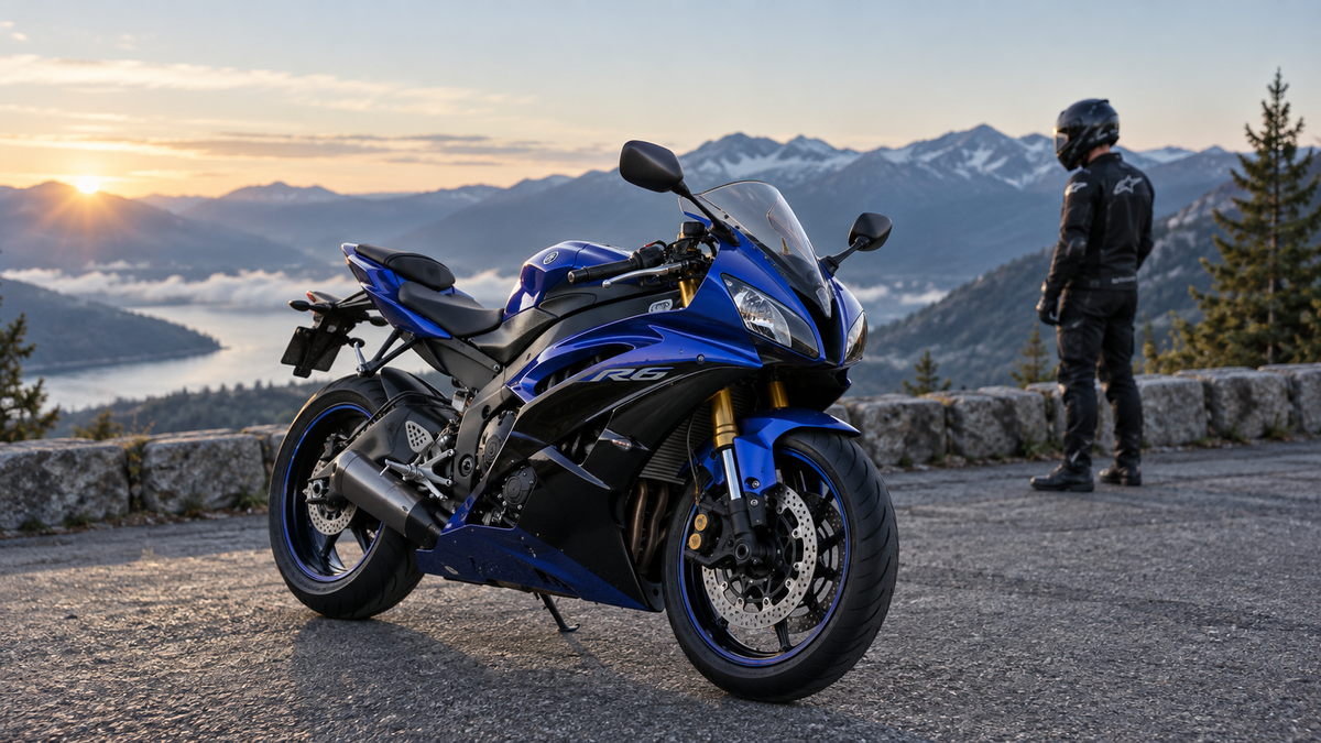
When a replacement upper cowl on a 2008–2016 Yamaha YZF-R6 seems one screw away from fitting, that last screw is often the warning. The nose assembly is a shared interface: the front stay supports the headlight and instruments, the upper cowl wraps around the light openings, the windscreen bridges the top edge, and the mirror bases add another pair of locating points. Pulling one hole into place can shift every seam around it.
This guide is for a complete street-style front assembly, not universal race bodywork. Yamaha specifications, regional equipment and previous repairs can differ, so confirm the model identity and use the service information for the exact motorcycle. The aim is to diagnose alignment without using painted ABS as a lever.
First Confirm That the Motorcycle Is in the 2008–2016 R6 Group
Do not identify an R6 from color alone. Registration documents, VIN information, existing part numbers and clear photographs all belong in the ordering record. A fairing listing that says only “R6” is incomplete because the model has more than one bodywork generation.
Photograph the complete left side, right side, centered front, centered rear and instrument area before removing anything. Add close-ups of the headlight shape, windscreen mounting pattern, mirror bases and the inner face of any retained panel. If the motorcycle already has replacement bodywork, do not assume its fasteners or labels are the correct reference.
For a broader generation comparison, use the Yamaha R6 2008–2016 versus later-bodywork guide. This article stays with the 2008–2016 front interface and does not claim interchangeability outside it.
Treat the Nose as Five Connected Systems
Separate the assembly into five systems before troubleshooting:
- Support: the front stay and any brackets that carry the light, instruments or upper cowl.
- Lighting: the headlight housing, its mounts, connectors and the opening around it.
- Painted bodywork: the upper cowl and the side-panel edges that meet it.
- Transparent and exterior parts: windscreen, mirrors and their mounting hardware.
- Isolation hardware: grommets, collars, washers, well-nuts and model-specific fasteners.
A visible gap at the headlight can originate in any of these systems. Replacing the cowl alone will not straighten a moved stay, reseat a folded grommet or correct a windscreen fitted on the wrong side of the painted edge.

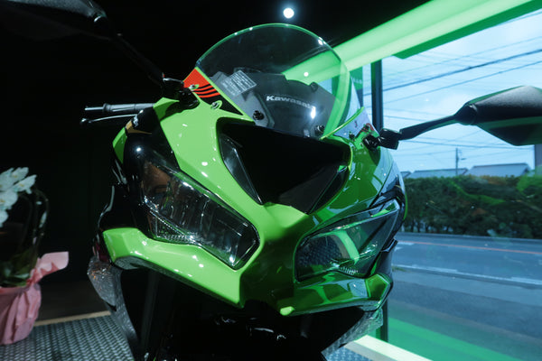
Editorial illustration: use the whole headlight–cowl–windscreen relationship as a diagnostic view; this image is not dimensional fitment evidence.
Build a Hardware Map Before Disassembly
Use a divided organizer or a piece of cardboard labeled by location. Keep left and right fasteners separate even when they look identical. Record which locations use a collar, rubber grommet or shouldered screw.
The official Yamaha parts diagram for a 2008 R6 cowling lists separate grommets and collars in the assembly. That is a useful reminder that a bolt is only one part of the stack. It does not prove that every 2008–2016 market specification uses the same part number in every location. Check the diagram and service data tied to your VIN and market.
Inspect retained rubber parts for tears, hardening or deformation. A new painted kit installed over collapsed rubber hardware can sit too close to the light on one side and too high near the windscreen on the other. Replace components by specification rather than choosing a generic piece because its diameter looks close.
Check the Front Stay Before Blaming the New Cowl
With the motorcycle stable and the battery handled according to the service procedure, inspect the front support from several angles. Look for cracked coating, fresh tool marks, distorted slots, unequal mirror-mount height or a headlight that is already off-center before the painted cowl is fitted.
Do not bend the stay until the new panel appears to match. A visual correction can move the headlight aim, instrument position or mirror relationship. If the motorcycle has been dropped or the stay looks altered, measure it using model-specific references or have a qualified technician assess it.
You can make a simple non-dimensional record by placing the camera on the motorcycle centerline and photographing the left and right mounting points at the same height. The photo will not certify alignment, but it can reveal a gross asymmetry and give a supplier or technician useful context.
Seat the Headlight Before Evaluating Its Perimeter Gap
The headlight must be supported in its intended mounts before its relationship to the upper cowl means anything. Confirm that its mounting points are intact, its connectors are routed safely and no wire bundle is trapped between the housing and support.
Offer the upper cowl to the installed light without fasteners first. The light openings should approach the housing without one edge carrying the entire load. If the cowl touches at one corner while the opposite side remains far away, stop and check the light position, bracket and panel overlap.
Never use a screw beside the headlight to pull the painted edge inward. Static tension around a narrow opening can produce stress whitening or a crack after vibration and heat cycles. A clean headlight seam comes from the locating parts agreeing, not from greater torque.
Dry-Fit the Upper Cowl With Every Mount Loose
The useful dry-fit sequence is controlled rather than fast:
- Place protective material over vulnerable painted edges.
- Confirm the headlight and front stay are seated and supported.
- Position the upper cowl, engaging designed tabs and grommets without forcing them.
- Add the side interfaces, mirror bases and windscreen only as needed to establish the complete geometry.
- Install all verified fasteners finger-tight.
- Center the headlight openings and compare left and right seams.
- Check the windscreen curve and every mounting hole.
- Tighten only in the sequence and to the values specified for the motorcycle.
If adding a mirror base or windscreen suddenly closes one gap and opens another, do not accept the change as normal. Remove that load and inspect the stack beneath it.
Let the Windscreen Reveal Stored Tension
The windscreen spans the upper edge and is sensitive to twist. Place it on the cowl without pressing down. Each hole should approach its well-nut or mounting point naturally. If the screen rocks, sits high at one corner or must be flattened by screws, determine whether the upper cowl is twisted, a well-nut is displaced or the screen is the correct application.
Over-tightening can crack a screen, distort the painted edge or spin a well-nut. Follow the service information and the screen manufacturer’s instructions. Do not apply thread-locking compounds to plastic assemblies unless the specific product and location allow it; some chemicals can damage plastic.
Examine the screen from the rider’s viewpoint as well as from outside. Confirm that it does not interfere with the instrument area and that no sharp fairing edge is bearing directly against it.
Use the Mirror Bases as a Final Check, Not a Clamp
The mirrors connect the outer bodywork to the support structure. Their bases should sit cleanly when the underlying parts are aligned. If tightening a mirror base is required to flatten a lifted cowl, the assembly still contains a mismatch.
Inspect rubber pads, spacers and the order of parts at each base. Compare left and right. Confirm that wiring for integrated signals, where fitted, is not pinched. After assembly, test the mirrors and electrical functions according to the owner or service information.
Diagnose the Pattern, Not Just the Largest Gap
| Alignment pattern | Inspect first | Avoid |
|---|---|---|
| Headlight gap narrow on one side and wide on the other | Headlight seating and front-stay symmetry | Pulling the wide side inward with its screw |
| Windscreen holes align on one side only | Upper-cowl twist, well-nut position and screen application | Enlarging painted holes before diagnosis |
| Mirror base lifts the cowl | Spacer order, support position and trapped wiring | Using the mirror nut as a clamp |
| Side panel meets the nose but the headlight seam moves | Panel overlap and installation sequence | Final tightening before all panels are present |
| Hole aligns only when the panel is flexed hard | Wrong part, missing hardware or moved support | Leaving ABS under permanent load |
| Both sides look even but steering contact occurs | Cable, lever, mirror and wiring clearance | Assuming visual symmetry equals safe operation |
This pattern-based record is more useful than saying “the fairing does not fit.” It tells a supplier or technician exactly which relationship changes when a part is added.
Do Not Drill or File a Painted Panel as the First Fix
Changing a hole can conceal the evidence needed to identify the actual problem. It may also expose paint, reduce edge distance and affect a return or support request. Before any irreversible alteration, document the complete assembly and contact the supplier with the model information, order record and photographs.
If a professional determines that a small correction is appropriate, protect the finish and follow their method. The decision should come after the support, headlight, hardware and panel identity have been verified.
Record the Exact Panel You Need
The phrase “front fairing” can mean an upper cowl, a side panel, an inner trim or an entire kit. Use the R6 and R3 fairing diagram identification guide to build a clearer request, then add real photographs of your motorcycle.
Send the supplier:
- Confirmed model year, market and VIN-derived model information where appropriate.
- A complete front view and both front three-quarter views.
- Close-ups of the headlight perimeter, windscreen holes and mirror bases.
- Photos of all affected inner tabs and retained brackets.
- The hardware layout, including collars and grommets.
- A description of which part changes the alignment during dry-fit.
- Information about retained aftermarket screens, mirrors or brackets.
Do not crop so tightly that the mounting context disappears. Pair every detail with a wider location photo.
Final Safety and Function Check
Before riding, complete a static inspection:
- Every tab is seated on the intended side of its mating part.
- Correct grommets, collars and fasteners are installed.
- No headlight or windscreen edge is under visible stress.
- Mirrors are secure and any signal wiring functions correctly.
- Headlight functions and aim are checked through the proper procedure.
- Handlebars move from stop to stop without touching bodywork or stretching wiring.
- Brake and clutch controls operate freely.
- No harness is trapped against a sharp edge.
- Lower and side panels remain clear of hot components.
Take a short first ride close to home only after the stationary checks pass. Reinspect the cooled motorcycle for fresh witness marks, loose fasteners or changed seams.
Alignment Comes From the Structure Outward
The 2008–2016 YZF-R6 nose should be assembled as a connected system. Confirm the motorcycle identity, map the hardware, establish the stay and headlight position, then let the upper cowl, windscreen and mirror bases meet without force.
That process takes longer than tightening the nearest screw, but it preserves the paint and exposes underlying problems while they are still easy to document. A front cowl that sits naturally is the result of correct interfaces—not a panel held in place by stored tension.