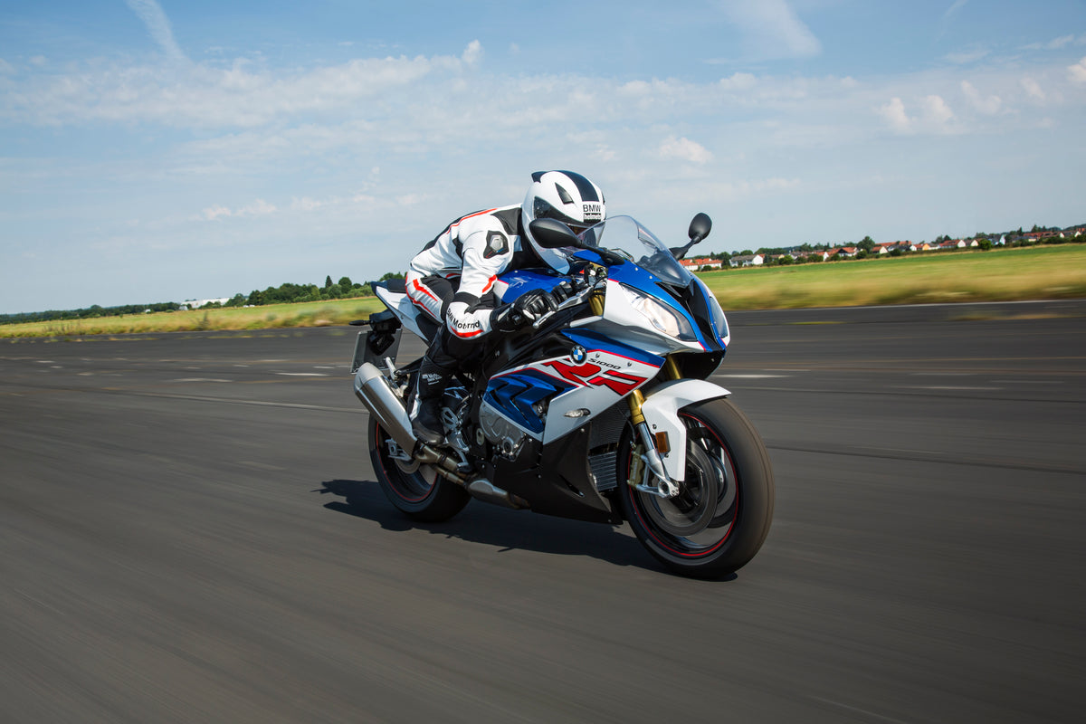
Lay a BMW S1000RR 2017–2018 fairing set on the floor and the two sides can look like mirror partners. They are not. The headlight surrounds follow different openings, the side-panel ventilation is asymmetric, and a graphic that looks balanced on loose pieces can read incorrectly once installed.
The safest workflow is to identify each piece by physical geometry first, record vehicle left and right from the rider’s seated position, and only then approve paint, decals or installation. This article uses official 2017-model imagery as a visual reference and real loose-panel photographs from a documented 2017–2018 kit. Those references support visual identification; they are not dimensional fitment certification for every motorcycle or every market.
Define Left and Right From the Rider’s Seat
Vehicle left and right never change with the camera angle. Sit mentally on the motorcycle facing forward:
- Vehicle left is the rider’s left.
- Vehicle right is the rider’s right.
- A front-facing photograph reverses those positions on the screen: vehicle right appears on the image’s left.
Write the convention at the top of every photo sheet. Avoid labels such as “photo left,” “piece A” or “the big opening side” unless the document also states the vehicle side. This becomes especially important when a supplier, painter and installer are looking at different images.
Use removable labels on the inner surface, away from finished paint and heat. Mark `L` and `R`, the photo filename and an arrow pointing forward. Never write directly on a visible surface.
Why This S1000RR Cannot Be Treated as a Mirrored Design
The 2017-model S1000RR front has visibly different lamp shapes. The cowl pieces surrounding them therefore have different inner contours. The main side regions also present different vent structures: the documented official side views show a broad primary opening on the left side and multiple gill-like openings on the right.
This asymmetry is a useful identification tool. It also means an image editor, painter or buyer should not mirror a reference photograph to invent the opposite side. Mirroring changes the lamp shape, vent topology, exhaust position, chain side and graphic reading.
The rule is simple: use an actual left-side reference for the left panels and an actual right-side reference for the right panels.

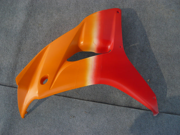
User-supplied production reference: the two nose pieces are identified by contour and opening geometry, not by assuming one is a mirror copy.
Identify the Nose Pieces by the Lamp Opening
Begin with the large cutout that wraps the headlight. Ignore paint and decals. Compare these features:
- The length and curvature of the inner lamp edge.
- The pointed upper and lower ends.
- The outer fold toward the side fairing.
- The number and position of visible holes.
- The mating edge that approaches the windscreen and center nose.
Use a centered front photograph of the complete motorcycle to relate each contour to the corresponding lamp. Remember that the vehicle-right cowl is displayed on the left side of a front-facing image.
Do not rotate a loose piece until its graphic “looks right” and then declare its side. Graphics can be applied incorrectly; the molded opening cannot be moved so easily. Geometry is the stronger evidence.
If a nose piece has been repaired, inspect the inner edge for added material or reshaping that may obscure its original contour. Pair the loose-part photo with the installed reference before making a decision.
Use Side Openings to Confirm the Main Panels
After the nose pieces, identify the main side regions. Look for the round badge area, the large molded opening, the upper/lower seam and the transition toward the radiator and lower cowl.
On the official visual references used for this 2017 model, the left side presents one dominant opening while the right side shows a group of gill-like openings. That observation is useful for this documented design. It does not prove that every aftermarket listing uses identical panel boundaries or that a later S1000RR panel interchanges.
Place the candidate piece beside a correctly oriented full-side photograph. Match the real opening shape and the direction of the pointed edges. Then check whether the fastener holes approach the correct support locations. Do not use the printed `RR` graphic or a roundel location as the first clue because paint layouts can vary.
Separate Outer Panels From Black Inner and Adjacent Pieces
A photograph of a loose kit may make a black insert look like part of a larger painted panel. Conversely, a same-color adjacent piece may appear fused to its neighbor. Before counting pieces, trace physical edges, tabs and mounting ears.
Record three categories:
- Painted exterior pieces with confirmed visual locations.
- Inner trims and duct pieces that are retained, supplied separately or still unidentified.
- Bagged or partially hidden components that cannot be counted from the image.
Do not convert the number of annotated photo regions into a claim about physical kit piece count. One review image can contain multiple parts, and one visual region can include a seam that is difficult to see.
When requesting a quote, ask for a written parts list and a photograph of the actual supplied set. “Complete fairing kit” is a commercial label; it does not universally define the same inner panels, tank trims, seat cover or hardware.
Treat the Tank and Seat Area as an Unresolved Interface Until Confirmed
The documented loose kit includes long, narrow paired covers and a central U-shaped piece whose installed coverage is not fully proven by the available photos. Their general shape may suggest a tank-side or rear-tank location, but that is not enough to call one a complete tank cover or a passenger-seat cowl.
This distinction matters because an incorrect name can cause three errors at once: the painter may place graphics on the wrong piece, the buyer may expect an item the kit does not contain, and the installer may try to force a trim into an unrelated location.
For ambiguous pieces, request:
- Inner and outer photographs.
- Overall dimensions used only for identification.
- Every hole, tab and mating edge.
- A wider installed photograph showing both ends.
- Confirmation of what OEM component is retained beneath or beside it.
Leave the part labeled “unconfirmed center trim” until the evidence supports a specific name.
Build a Left/Right Contact Sheet Before Approving Color
Create a two-column document with vehicle left on one side and vehicle right on the other. Each row should show the same region: nose, main side, lower side, tank-side trim and tail.
| Region | Vehicle-left evidence | Vehicle-right evidence |
|---|---|---|
| Headlight surround | Actual left lamp contour and cowl opening | Actual right lamp contour and cowl opening |
| Main side region | Single dominant opening in reference | Multiple gill openings in reference |
| Lower side | Seam and fastener path from actual left view | Seam and fastener path from actual right view |
| Exhaust/chain context | Use only as orientation confirmation | Use only as orientation confirmation |
| Graphics | Approved after geometry | Approved after geometry |
Place the official reference, loose-panel photo and proposed artwork in each cell. A reviewer should be able to follow one feature from the whole motorcycle to the bare part and finally to the graphic.
This contact sheet prevents a common design mistake: making both sides visually identical when the panel shapes are different. A diagonal stripe may cross an opening cleanly on the left yet collide with the right-side gills.
Adapt the Graphic to Each Panel Instead of Mirroring It
Once panel identity is stable, evaluate the artwork at real seams and openings. Keep important letters, number outlines and sponsor marks away from bolt recesses and sharp folds. Decide whether a stripe should stop at a seam or continue across two separately installed parts.
A symmetrical color balance does not require identical graphic geometry. The left and right layouts can share colors and visual weight while using different paths around the openings.
Ask for both installed-side mockups before approving paint. A single hero view hides the opposite side and cannot confirm the complete design. If the mockup is AI-generated, label it as a concept and compare it with the original official left and right motorcycle photographs. AI output can invent vents, close holes or move logos.
Do Not Use the Current Concept Renders as Fitment Proof
Previous experimental renders in the model reference improved color placement but also introduced errors: an unsupported tail logo, incomplete tank coverage, misplaced graphics and reconstructed text. They remain review drafts.
This is exactly why a generation image must not become the next generation’s base. Each new concept should return to the original motorcycle photograph and the original loose-panel references. Otherwise, invented details accumulate.
For ordering, rely on the motorcycle identity, real parts, supplier documentation and actual mounting evidence. For styling, use the concept only to discuss color direction and graphic balance.
Installation Check After the Pieces Are Labeled
Correct left/right labeling does not guarantee installation. Before final tightening:
- Verify the motorcycle and kit scope.
- Inspect every tab, grommet, collar and bracket.
- Dry-fit painted pieces with all fasteners loose.
- Confirm the headlight-cowl edges and the different side openings remain free.
- Check adjacent inner trims rather than using the outer panel to pull them into place.
- Tighten only in the model-specific sequence and specification.
- Test steering, controls, lights and clearance from hot components.
Never use a bolt to force a mislabeled or mispositioned panel across the motorcycle. If the geometry disagrees, stop and recheck orientation, hardware and support structure.
For a dropped motorcycle, the broader BMW S1000RR repair-or-replace guide helps define whether the problem is one panel, a coordinated set or an underlying support.
Supplier Photo Checklist
Send this package before approving a custom set:
- VIN-confirmed model information and target year range.
- Full left and right views of the actual motorcycle.
- Centered front view showing both asymmetric lamps.
- Inner and outer views of every nose piece.
- Main side panels photographed square-on with openings visible.
- Close-ups of tabs, holes and mating edges.
- Written kit contents, retained OEM pieces and hardware policy.
- Separate left and right color mockups.
- A list of any unresolved component names.
If a replacement is being matched to the current motorcycle, add neutral-light paint photographs. Do not promise a perfect match from a screen image; existing finish, camera white balance and display settings all influence appearance.
Final Review Before Paint or Installation
- Left and right are defined from the seated rider’s perspective.
- Front-facing photos have been interpreted correctly.
- Nose pieces match the actual lamp-opening contours.
- Main side panels match the actual opening topology.
- No reference image was mirrored to invent the opposite side.
- Ambiguous tank or seat-area pieces remain clearly labeled as unconfirmed.
- Kit piece count comes from a written inventory, not annotation boxes.
- Both graphic sides have been reviewed at seams and openings.
- AI concepts are not being used as fitment evidence.
- Installation will begin with a loose dry-fit and verified hardware.
Asymmetry Is the Identification Key
The 2017–2018 S1000RR’s asymmetry is not an obstacle once it becomes the organizing principle. The headlight openings identify the nose pieces, the side vents help confirm the main panels, and separate left/right references keep graphics honest.
Label by geometry, preserve unresolved parts as unresolved, and review each side independently. That method is slower than mirroring a photo, but it prevents a visually convincing mistake from reaching paint or installation.