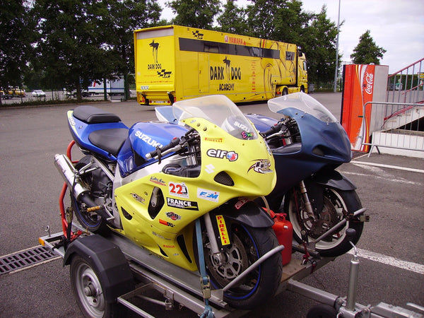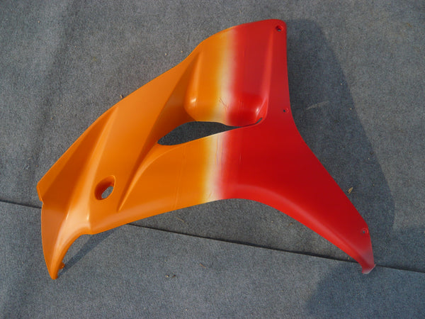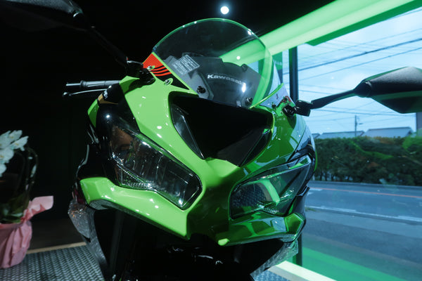

Cover disclosure: AI-generated editorial concept. It is not an installation record, wiring diagram, product endorsement or model-specific fitment reference.
Adding a dashcam, compact navigation display, phone-power lead or tire-pressure receiver to a sportbike is not primarily a question of hiding wire. It is a movement-and-clearance problem. The route must remain clear when the handlebars move, the fork and suspension work, panels are installed, heat builds and technicians later need to remove the bodywork.
Before opening the motorcycle, obtain the correct service information and the accessory manufacturer's instructions. If the work involves the charging system, fused power, grounding, waterproof connectors or uncertain current draw, use a qualified motorcycle electrician. This guide focuses on documenting space around fairings; it does not provide a universal wiring diagram.
Key takeaways
- Inventory each component, cable, connector and converter before choosing a route.
- Record full steering movement and all existing harness paths with the motorcycle stationary and safely supported.
- Never use a fairing fastener or panel seam to clamp a wire.
- Keep added wiring away from heat, sharp edges, steering stops, controls and moving suspension parts.
- Confirm which inner trims, ducts and clips are actually supplied; a “complete kit” is not a universal contents promise.
- Photograph the route before closing panels so the next technician does not have to guess.
The decision to make before the fairings go back on
Before buying a mount or closing the nose, answer three questions: where can the device be supported, where can its largest connector travel without interfering with the motorcycle, and how will a technician disconnect it later? The existing steering-clearance checklist covers the final full-lock check; the fairing-openings guide helps identify the original interfaces. Here the focus is the earlier route decision, before drilling, bonding or final assembly.
It does not claim that newer replacement plastics create extra space. The available envelope comes from the documented motorcycle, retained components, accessory dimensions and supported installation method.
Begin with an electronics inventory
Lay out every item on a clean bench without connecting it to the motorcycle. Include the display, front and rear cameras, control or recorder module, power converter, fuse holder, connectors, extension leads, microphone or GPS antenna where applicable, and every supplied mount. Measure the large parts and the connector heads, not only cable diameter.
Create four columns: component, intended location, cable destination and service action. A front camera may be small but its connector may require a much larger path. A converter box may fit behind a panel but become unreachable without removing several pieces. A display mount may clear the windscreen at centre while touching at full steering lock.
Record which items need airflow, weather protection or a defined orientation according to their manufacturer. Do not seal a device inside foam or an improvised bag unless its instructions support that arrangement.
Photograph the unmodified baseline
Before removing anything, take straight-ahead, left-lock and right-lock cockpit photographs. Add views behind the windscreen, beside the headlight, under the tank edge and along the tail route if a rear camera is planned. Photograph existing clips, rubber guides, grommets and connectors before releasing them.
These photographs separate original routing from new work. They also help identify whether a damaged inner trim or missing clip existed before the electronics project. When considering replacement bodywork, start with the correct family—Yamaha fairings, Honda fairings, Kawasaki fairings or Suzuki fairings—but verify the exact model, year and written contents. A collection page does not prove that inner cockpit pieces or harness stays are included.
Build a no-wire zone map
Mark areas that added wiring must not enter. The list normally includes steering stops, fork tubes, control cables, brake hoses, throttle movement, hot components, sharp brackets, moving suspension parts, radiator fans and openings used for intended airflow. Exact zones depend on the motorcycle; do not copy a photograph from another model.
Move the handlebars slowly only as the correct service procedure permits. Watch what approaches the inner cowl, windscreen edge and headlight stay. A cable can appear loose at centre and become taut or folded at one lock. Check the entire cable bundle, not just the visible section near the display.
Use removable tags to mark questions during planning. Do not drill, cut, glue or tighten a permanent tie while the route is still unresolved.
Treat ram-air and inner-cowl areas as functional spaces
A void behind the nose is not automatically spare storage. It may contain a duct, lighting hardware, a support stay, factory harness routing or the movement envelope of another part. Blocking or narrowing a duct to hide a converter box is not a cosmetic decision. If the installation would alter an air path or a structural support, stop and obtain model-specific guidance.
Likewise, do not squeeze a connector between two panels because it disappears from view. Panel seams need to sit without pressure. A trapped connector can create a gap, a rub mark or a stressed attachment, and the fastener may conceal the problem until the panel cracks.
Choose attachment points without inventing structure
Use only mounts and attachment methods supported for the device and motorcycle. A fairing tab is intended to locate bodywork; it is not automatically a camera bracket. A windscreen fastener may not be approved to carry an extra arm. Adhesive performance depends on surface, preparation, temperature, load and product specification.
Separate the camera's viewing requirement from its mounting requirement. First choose the field of view and check that the bodywork does not obscure it. Then identify a supported mount. Do not solve one problem by compromising the other.
For a rear camera, consider seat removal, tail movement, luggage, lighting visibility and the route forward. The shortest line on a diagram may cross the most service-sensitive area on the motorcycle.
Make a cable-routing worksheet
| Electronic component | Candidate concealment zone to assess | Clearance risk to avoid | Evidence before closing |
|---|---|---|---|
| Front camera | Supported area near nose or windscreen, if approved | Fork sweep, brake hose, headlight movement, blocked opening | Centre/left/right views and clear camera image |
| Compact display | Documented cockpit mount | Lever or windscreen contact; blocked instruments | Full-lock photos, seated sightline and control access |
| Rear camera | Supported tail or plate-area mount, subject to local rules | Tire/suspension movement, light obstruction, seat removal | Rear view, suspension clearance and cable service loop |
| Recorder/control module | Dry, supported location permitted by manufacturer | Heat, water pooling, crushed connector, loss of service access | Component dimensions and removal path |
| USB/power converter | Fused installation planned by a competent person | Unfused lead, sharp bracket, heat, trapped box | Wiring diagram, fuse location and secure support |
| TPMS receiver/display | Visible supported cockpit location | Steering movement and instrument obstruction | Full sweep and rider-view check |
“Candidate” matters: the actual location must be confirmed for the exact bike and accessory. The table is a planning record, not permission to place a component in any named area.
For example, suppose a proposed front-camera connector fits behind a loose nose panel but pushes an inner trim outward when the screen is fitted. The route has failed even if the camera itself clears the fork. Record the interference, check the device's approved mounting and cable options, and revise the plan with a qualified installer. Do not use a screw to compress the connector into the gap. This is a hypothetical planning example, not a tested motorcycle installation.
Use grommets and edge protection correctly
When a supported route passes through an existing opening, inspect the edge and the original protection. Replace a damaged grommet only with an appropriate part. Do not assume a generic rubber ring is suitable for every thickness, environment or cable.
Avoid routing over cut plastic, unfinished metal or threads. Where the correct design uses a clip, guide or sheath, confirm that it is present and positioned as intended. Do not add a hole to painted bodywork merely because the wire will not fit through an existing seam.
Leave service allowance according to the equipment instructions without creating a loose loop that can reach moving parts. “More slack” and “safer” are not the same thing.
Perform a staged closure
Do not fully assemble the fairings in one step. With the system unpowered or handled according to the manufacturer's safe procedure, place the panels loosely and observe where the route changes. Confirm that no connector becomes a spacer between panels. Keep fasteners loose until every interface sits naturally; never pull a panel over a cable with bolt tension.
Then repeat the steering sweep and visual inspection. Check controls, hoses and wiring at centre and both locks. If safe and appropriate, verify that the display remains visible and that a camera view is not blocked. Remove the panels again and look for fresh witness marks before final closure.
The panel-gap diagnosis guide provides a useful first-conflict method when a seam changes after new equipment is added.
Separate old-plastic problems from routing problems
An aged inner trim may already have repaired tabs, enlarged holes or missing clips. Replacement may be appropriate after the part and cause are identified, but a fresh panel does not make an unsafe route safe. Conversely, a good route does not restore a fractured mounting point.
Create two lists: bodywork condition and electronics installation. For the first, identify damaged pieces, supports and required hardware. For the second, record power, mounts, cable paths and service access. Compare the lists only where they physically interact.
When contacting NiceFairings, send the exact motorcycle details and photographs through the custom fairings page or contact page. Ask which painted and inner pieces are included in the specific offer. Do not state that every kit supplies ducts, inner cowls, grommets or wire clips.
Create a handoff record
Save a simple diagram and photographs after the final route is approved. Mark the power source, fuse, ground, disconnect points, module locations and the first panel that must be removed for service. Attach the accessory manuals and receipts.
This record helps with troubleshooting and prevents a later technician from pulling on a hidden connector. It also lets a future owner distinguish a documented installation from unexplained wiring.
Plan power and fault isolation separately from concealment
A tidy cable route does not establish a safe electrical design. Record the accessory's stated input, fuse requirement, switching method and connection instructions, then have the plan checked by a competent person. Do not copy a wire color, fuse value or grounding point from another motorcycle or forum photograph.
The installation should allow the accessory system to be isolated and diagnosed without cutting the motorcycle's harness or dismantling unrelated panels. Label connectors in the private service record, not with large visible stickers that could detach inside the cockpit. Keep an accessible note of which fuse protects which added device.
After initial power-up according to the product instructions, check for fault messages, abnormal heat, intermittent operation and interference with original controls. Shut down if anything is unexpected. A dark display may be a power issue, not evidence that the cable needs to be pulled tighter through the fairing.
When the motorcycle already has alarms, heated grips, lighting changes or other electrical accessories, list them before adding another device. The modified-sportbike pre-order checklist is useful for documenting changes that may also affect replacement bodywork.
Review the route after ordinary service actions
Simulate only the safe, documented service movements relevant to the bike: windscreen removal, seat access or the first panel removal, for example. Confirm that a technician can disconnect the new equipment without hanging a panel by its cable. A service loop should support access without entering a moving or hot zone.
If an added mount blocks a factory fastener or hides a fluid reservoir, revise the layout. Electronics should not turn routine inspection into risky improvisation. Photograph the final service position and include it in the handoff record.
FAQ
Can I hide every wire behind the fairings?
Not necessarily. Safety, movement, airflow, weather protection and service access take priority over invisibility. Some supported routing may remain visible.
Does a complete replacement fairing kit include inner cockpit plastics?
There is no universal contents list. Confirm the exact product page and written quotation. Ask what is supplied, retained and bought separately.
Can I route a cable through a ram-air opening?
Do not obstruct an intended air path or assume an opening is spare. Use model-specific documentation and qualified guidance.
Is a zip tie enough?
The correct retention method depends on the location, cable and manufacturer instructions. A tie must never create abrasion, crush a cable or allow contact with moving or hot parts.
What should I test before closing the panels?
Check the documented steering sweep, control and hose clearance, cable movement, panel seating, camera view, display visibility, weather protection and service-disconnection plan.
Before the first ride
Have the installation reviewed by an appropriately qualified person when electrical or mechanical safety is uncertain. Recheck panel seating and the supported equipment procedure after the initial service interval recommended by the installer or manufacturer. A factory-clean appearance is the final visual result; the real standard is a documented route that remains clear, supported and serviceable.
Manufacturer reference and limits
Garmin's powered motorcycle mount instructions call for a secure location, safe cable routing and an experienced electrical installer. Its zūmo R1 radar instructions specifically address cable allowance across the handlebars' turning range. These are examples of manufacturer requirements, not an installation specification for every dashcam, display or motorcycle. Use the instructions for the actual accessory and bike.